


Low Voltage Switchgear


01

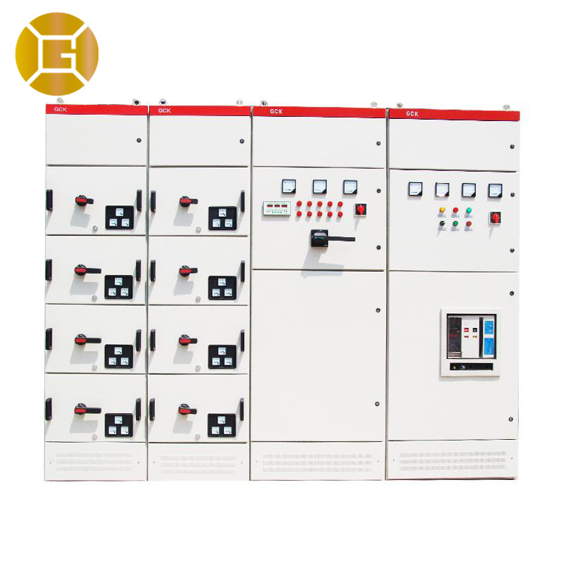
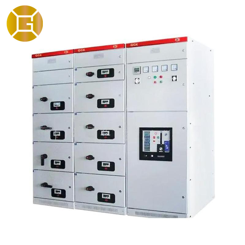
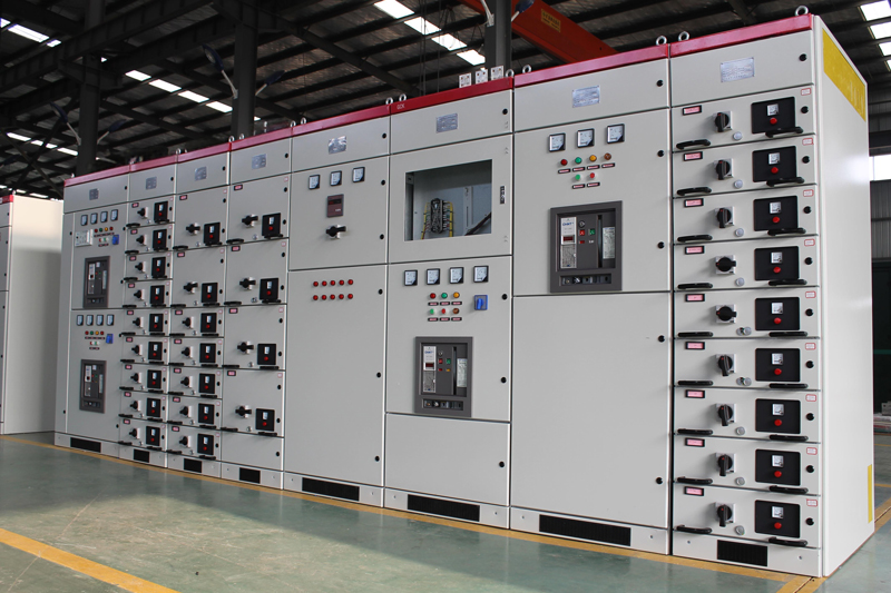
GCK Low Voltage Draw-Out Switchgear
Features
● The entire cabinet adopts a knockdown combined structure with modular hole mounting, featuring high component universality, strong adaptability, and a high level of standardization.
● The upper part of the cabinet is the busbar compartment, the front is the electrical compartment, and the rear is the cable inlet/outlet compartment. Each compartment is separated by steel plates or insulation boards to ensure safety.
● The door of the drawer compartment in the MCC cabinet is equipped with a mechanical interlock with the operating handle of the circuit breaker or isolating switch; the door can only be opened when the handle is in the open position.
● The incoming switch, tie switch, and drawers of the MCC cabinet have three positions: connected position, test position, and disconnected position.
● A busbar bridge can be installed on the top of the switchgear as per power-receiving requirements.
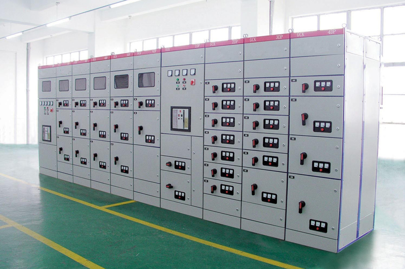
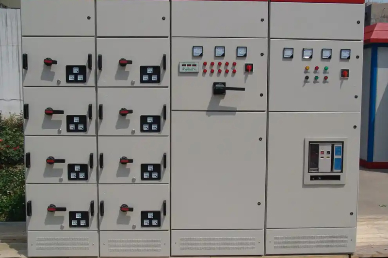
Operating conditions
● Environmental temperature: not higher than+40 ℃, not lower than -5 ℃; The average temperature within 24 hours shall not be+35 ℃; When exceeded, it is necessary to reduce the capacity and operate according to the actual situation;
● Altitude: not exceeding 2000m, for indoor use;
● Atmospheric conditions: The relative humidity of the surrounding air should not exceed 50% at a maximum temperature of+40 ℃, and a relatively high relative humidity is allowed at lower temperatures, such as 90% at+20 ℃. The influence of condensation due to temperature changes should be considered;
● When installing the device, the inclination with respect to the vertical plane shall not exceed 50 ℃, and the entire cabinet row shall be relatively flat (in accordance with GBJ232-82 standard);
● The device should be installed in a place where there is no severe vibration and impact, and where the electrical components are not subjected to the necessary corrosion;
Note: If any customized requirements, please consult with our company.
Technical specifications
|
Items |
Data |
|
| Rated operating frequency(Hz) |
50 |
|
| Rated working voltage(V) |
380,660 |
|
| Rated insulation voltage(V) |
660 |
|
| Rated working current(A) | Horizontal busbar |
630-3150 |
| Vertical busbar |
600 |
|
| Rated short-time withstand current | Horizontal busbar |
80kA(Effective value)/1 sec |
| Vertical busbar |
50kA(Effective value)/1 sec |
|
| Rated peak withstand current | Horizontal busbar |
176kA/0.1s |
| Vertical busbar |
110kA/0.1s |
|
| Main circuit connector(A) |
200, 400, 680, 800 |
|
| Auxiliary circuit connector(A) |
10 |
|
| Power frequency withstand voltage for 1 min(V) |
2500 |
|
| Protection level |
IP40 |
|
| Operation mode |
On site, remote, automatic |
|
Note: The above data is subject to change due to technical improvement.