inquiry
Inquiry
Form loading...
0%

When it comes to Reliable Power, it all starts with choosing a transformer that's perfectly suited to its load, location, and operating conditions. Did you know that according to the International Energy Agency’s Electricity 2024 report, global electricity demand increased by 2.2% in 2023? And it’s projected to grow about 3.4% each year from 2024 through 2026. Now, these numbers aren’t meant to predict what every single facility will need — but they do highlight why picking the right distribution equipment is so crucial.

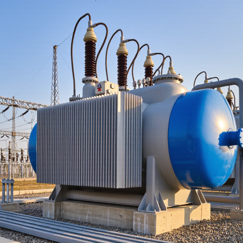
Take, for example, an 11kV to 400V step-down Oil-immersed Transformer. It basically turns medium-voltage power into lower voltage energy that a lot of commercial and industrial setups rely on. The oil inside helps insulate and cool things down, while the tank, cooling surfaces, and safety devices all work together to keep it running smoothly. But here’s the thing — just looking at the nameplate isn’t enough. Factors like how your load fluctuates, the temperature outside, installation space, how you run your cables, and easy access for maintenance all play a role in how well it’ll perform in real life. Honestly, those small details really do matter.

This guide shares five practical tips to consider when evaluating a Step Down Transformer. We cover everything from number ratings and connections to cooling, protection, and routine checks. The goal here isn’t to replace a pro engineer’s site assessment — it’s about helping you ask better questions before you go ahead and specify or install equipment. Keep in mind, no checklist can cover every single site condition. That’s something you should always be aware of. Even if a transformer is rated correctly, it can still let you down if the working environment or future load changes aren’t taken into account.
5 Tips for 11kV 400V Oil Immersed Step Down Transformers

Set System Basics: 11 kV/400 V, 50 Hz, 400 V Line and 230 V Phase-to-Neutral

An 11 kV/400 V oil-immersed transformer reduces medium voltage to a low-voltage supply. In a three-phase, 50 Hz system, 400 V is the nominal voltage between phases. The voltage from any phase to neutral is about 230 V, since 400 divided by the square root of three is approximately 231. These are nominal values; actual readings can vary with supply conditions and load.

Tip: Check the nameplate and connection diagram before selecting or connecting loads. A 400 V three-phase load typically uses the phase conductors, while a 230 V circuit uses one phase and neutral, where the system design allows. Confirm the neutral arrangement, vector group, and phase sequence with suitable test equipment. Small details matter.

The arithmetic is tidy, but real readings shift with load and incoming voltage. Before energizing, have qualified personnel verify earthing, protective devices, connections, and Insulation condition. Confirm the tap position against the supply voltage and manufacturer instructions; never operate an off-circuit tap changer while energized. Oil condition and leaks also deserve inspection. A quick visual check can miss a problem.

Size kVA for Demand, Motor Starts, and Growth; Follow Nameplate Loading

5 Tips for 11kV 400V Oil Immersed Step Down Transformers

Size the transformer from measured demand, not the sum of every connected load. Record peak kW and power factor, then convert to kVA. Check motor starting separately: a pump or compressor can briefly draw several times its running current. That short surge may cause voltage dip even when average demand looks modest. Leave room for planned growth, but avoid oversized equipment that runs lightly loaded for years. The U.S. Department of Energy’s 2016 Distribution Transformers Technical Support Document uses 50% of rated load in its efficiency analysis; this is a comparison point, not a universal sizing target.

Tip: List the largest motors, starting method, and start frequency. Ask the supplier or a qualified engineer to check voltage drop and starting duty against the actual load profile. Small details matter. A neat spreadsheet can still miss a seasonal pump or a future workshop.

Follow the nameplate kVA, voltage, frequency, cooling, and temperature-rise ratings. Do not treat brief overload capability as continuous capacity. Check oil and ambient conditions, ventilation, protection settings, and phase balance during commissioning. For single-phase applications, a Single-phase oil-immersed transformer needs its own demand assessment; a D11-M Series designation does not verify suitability. Single-phase oil-immersed transformers possess several key advantages, but nameplate limits and site measurements should guide selection. Recheck loading after new motors or equipment are added.

Confirm 12 kV Insulation: 28 kV AC and 75 kV Lightning-Impulse Withstand

For an 11 kV transformer, confirm that the insulation class matches the system’s highest equipment voltage, typically 12 kV. IEC 60076-3 lists 28 kV power-frequency withstand and 75 kV lightning-impulse withstand as standard insulation levels for this voltage class. These are test withstand values, not normal operating voltages. Check the project specification and applicable edition of the standard before approving a design.

Ask for the test record, not just a nameplate claim. It should identify the applied voltage, test duration, impulse waveform, and acceptance criteria. The 75 kV impulse test represents fast overvoltage stress, such as a lightning surge; the 28 kV AC test checks insulation under sustained power-frequency stress. Small details matter. Inspect bushings, clearances, and cable terminations, where installation conditions can undermine an otherwise sound design.

For an 11Kv Oil Immersed Power Transformer for Outdoor Use, also consider altitude, pollution, and surge protection when reviewing insulation coordination. IEC values provide a useful baseline, but they do not replace site-specific engineering. A clean test sheet can still leave questions. Ask whether the tested configuration matches the supplied unit, and keep the report with commissioning records.

Select Vector Group and Taps; ±2 × 2.5% Off-Circuit Taps Are Common

For an 11kV/400V oil-immersed step-down transformer, off-circuit taps help match the primary winding to the supply voltage. A common arrangement is ±2 × 2.5%, giving five positions: −5%, −2.5%, nominal, +2.5%, and +5%. The exact tap markings can vary, so check the nameplate and connection diagram rather than relying on convention alone.

Choose a setting from measured supply conditions, not guesswork. For example, if the incoming voltage consistently sits above its rated value, a lower-voltage tap may help keep the secondary near 400V. The direction can be confusing: confirm how the manufacturer labels each position.

Small detail. Tap changes are made only when the transformer is de-energized and safely isolated by qualified personnel. After adjustment, verify the secondary voltage under realistic load; a no-load reading may not tell the whole story.

Taps correct a persistent voltage mismatch, not rapid supply swings or every load-related voltage drop. Record the selected position and the readings used.

Vector group selection matters too, especially where phase shift or neutral arrangements must match the installation. In practice, site readings can be imperfect, and one visit may not capture seasonal variation. Recheck when operating conditions change.

Apply IEC 60076-2 ONAN Rise Limits: 60 K Oil and 65 K Winding

For an 11kV Outdoor Oil Immersed Power Transformer operating with ONAN cooling, IEC 60076-2 gives useful temperature-rise limits: 60 K for the top oil and 65 K for average winding temperature. These figures describe rises above the cooling air, not the transformer’s absolute temperatures. That distinction matters. At 40°C ambient, a 60 K top-oil rise means roughly 100°C at the measurement point.

The limits help engineers assess thermal performance during specified tests, but they are not interchangeable readings. Top-oil temperature is measured in the tank, while winding temperature rise is commonly determined through test methods such as resistance measurements. Winding hot spots can run hotter than the average. A compliant average, by itself, does not describe every point inside the coil.

For a practical review, check the cooling arrangement, test conditions, ambient temperature, and the manufacturer’s declared values against the applicable IEC requirements. Look closely at sensor placement and test records; small details can affect interpretation. Oil level, radiator cleanliness, and clear airflow also influence heat removal in service. A tidy report is reassuring, though it can still leave questions about actual site conditions. Better to verify than assume.

Commission Safely: Check Ratio, Insulation Resistance, and Oil Condition

Before energizing an 11kV Oil Immersed Transformer, confirm its nameplate, tap position, and approved connection diagram. Use calibrated ratio-test equipment to compare each phase with the expected 11kV-to-400V ratio. Check the vector group and polarity too; a correct ratio alone cannot confirm that connections are right. Record the readings. Each phase should meet the equipment tolerances and site test procedure. If results differ, stop and investigate instead of changing taps by guesswork.

Measure insulation resistance between windings and from each winding to earth, following the approved test procedure. Isolate sensitive accessories, use the specified test voltage, and note winding temperature, humidity, and test duration. Resistance varies with temperature, so compare corrected readings rather than treating one value as a verdict.

Inspect the oil level, sight glass, seals, radiators, and bushings for leaks, cracks, or trapped air. A qualified technician can assess oil condition through clean sampling and suitable moisture and dielectric-strength tests. Keep the sample clean; a hurried bottle can distort results. It is an easy detail to overlook.

Review test records, verify protective devices, and resolve abnormal findings before energizing.

Three-Phase Oil-Immersed Transformers: Insights from the U.S. DOE’s 2024 National Transformer Roadmap

The U.S. Department of Energy’s 2024 National Transformer Roadmap draws attention to the importance of reliable, efficient transformers as electricity systems evolve and demand for grid equipment grows. It frames transformer readiness as a practical challenge involving dependable performance, energy efficiency, manufacturing capacity, and careful planning. These priorities make equipment selection significant: utilities and project developers need solutions that can support stable operation while managing losses, noise, and space requirements.

The S(B)11/13/20/22-M Series oil-immersed transformers are designed with these considerations in mind. Superior technology and equipment, careful material selection, and efficient manufacturing contribute to a compact, lightweight design with low losses, low partial discharge, and low noise. Their stable and reliable operation can help meet varied distribution needs, while their economical and environmentally friendly characteristics align with the broader focus on building a resilient, efficient power network. As roadmap discussions encourage attention to both present reliability and future system needs, transformer attributes such as performance, durability, and efficient use of resources remain central to infrastructure decisions.

FAQS

What does an 11 kV/400 V transformer do?

It reduces medium voltage to a low-voltage supply. The stated system uses three phases at 50 Hz.

What do 400 V and 230 V mean in this system?

400 V is the nominal voltage between phases. About 230 V is measured from one phase to neutral.

Can actual voltage readings differ from these values?

Yes. Supply conditions and load can shift readings. Nominal values are not guarantees.

What should be checked before connecting a load?

Check the nameplate, connection diagram, neutral arrangement, vector group, and phase sequence. Small details matter.

What should be verified before energizing the transformer?

Qualified personnel should check earthing, protective devices, connections, insulation, and tap position. Do not operate an off-circuit tap changer while energized.

What are the ONAN temperature-rise limits described in the article?

The stated limits are 60 K for top oil and 65 K for average winding temperature. These are rises above cooling air.

What would a 60 K top-oil rise mean at 40°C ambient?

It would indicate roughly 100°C at the measurement point. A simple example, not every operating condition.

Why might average winding temperature not tell the whole story?

Winding hot spots can be hotter than the average. Sensor placement and test methods also affect interpretation.

What practical checks can support cooling and temperature review?

Review test conditions and records, then inspect oil level, radiators, and airflow. A tidy report can still miss site issues.

Conclusion

Choosing an 11kv 400v step down oil immersed transformer starts with confirming the system requirements: an 11 kV primary, 400 V three-phase secondary, and 50 Hz frequency. In a typical 400/230 V system, 400 V is the line-to-line voltage and 230 V is the phase-to-neutral voltage. Size the transformer for expected demand, motor-starting currents, and future growth, while keeping operation within its nameplate rating. For a 12 kV insulation class, verify that the specified withstand levels include 28 kV AC and 75 kV lightning impulse.

Also confirm that the vector group suits the installation and that the voltage taps can accommodate supply variations; ±2 × 2.5% off-circuit taps are common. Check temperature-rise limits against IEC 60076-2, typically 60 K for oil and 65 K for windings. Before energizing, commission the unit safely by checking the voltage ratio, insulation resistance, and oil condition, and ensure that the results meet the transformer’s specifications.
Isabella

Isabella

Isabella is a dedicated marketing professional at Jiangxi GUOXIANG Electric Power Equipment Co., Ltd., where she has been instrumental in shaping the company’s online presence since its establishment in 2016. With a deep understanding of the company's extensive range of integrated power solutions,......
Previous How to Choose the Best Prefabricated Substation?